
- BY Admin
- POSTED IN Articles
- WITH 0 COMMENTS
- PERMALINK
- STANDARD POST TYPE
Invented by An IBM team lead by Rey Johnson
Connects to Host adapter of system, in PCs typically integrated into motherboard. via one of:
* PATA (IDE) interface
* SATA interface
* SAS interface
* SCSI interface (popular on servers)
* FC interface (almost exclusively found on servers)
* USB interface
Market Segments Desktop computers
Mobile computing
Enterprise computing
Consumer electronic
A hard disk drive (often shortened as hard disk, hard drive, or HDD) is a non-volatile storage device that stores digitally encoded data on rapidly rotating platters with magnetic surfaces. Strictly speaking, “drive” refers to the motorized mechanical aspect that is distinct from its medium, such as a tape drive and its tape, or a floppy disk drive and its floppy disk. Early HDDs had removable media; however, an HDD today is typically a sealed unit (except for a filtered vent hole to equalize air pressure) with fixed media.
History
Main article: History of hard disk drives
HDDs (introduced in 1956 as data storage for an IBM accounting computer) were originally developed for use with general purpose computers. During the 1990s, the need for large-scale, reliable storage, independent of a particular device, led to the introduction of embedded systems such as RAIDs, network attached storage (NAS) systems, and storage area network (SAN) systems that provide efficient and reliable access to large volumes of data. In the 21st century, HDD usage expanded into consumer applications such as camcorders, cellphones (e.g. the Nokia N91), digital audio players, digital video players, digital video recorders, personal digital assistants and video game consoles.
Technology
Hard drive-en.svg
HDDs record data by magnetizing ferromagnetic material directionally, to represent either a 0 or a 1 binary digit. They read the data back by detecting the magnetization of the material. A typical HDD design consists of a spindle that holds one or more flat circular disks called platters, onto which the data are recorded. The platters are made from a non-magnetic material, usually aluminum alloy or glass, and are coated with a thin layer of magnetic material, typically 10-20 nm in thickness with an outer layer of carbon for protection. Older disks used iron(III) oxide as the magnetic material, but current disks use a cobalt-based alloy.
A cross section of the magnetic surface in action. In this case the binary data is encoded using frequency modulation.
The platters are spun at very high speeds. Information is written to a platter as it rotates past devices called read-and-write heads that operate very close (tens of nanometers in new drives) over the magnetic surface. The read-and-write head is used to detect and modify the magnetization of the material immediately under it. There is one head for each magnetic platter surface on the spindle, mounted on a common arm. An actuator arm (or access arm) moves the heads on an arc (roughly radially) across the platters as they spin, allowing each head to access almost the entire surface of the platter as it spins. The arm is moved using a voice coil actuator or in some older designs a stepper motor.
The magnetic surface of each platter is conceptually divided into many small sub-micrometre-sized magnetic regions, each of which is used to encode a single binary unit of information. Initially the regions were oriented horizontally, but beginning about 2005, the orientation was changed to perpendicular. Due to the polycrystalline nature of the magnetic material each of these magnetic regions is composed of a few hundred magnetic grains. Magnetic grains are typically 10 nm in size and each form a single magnetic domain. Each magnetic region in total forms a magnetic dipole which generates a highly localized magnetic field nearby. A write head magnetizes a region by generating a strong local magnetic field. Early HDDs used an electromagnet both to magnetize the region and to then read its magnetic field by using electromagnetic induction. Later versions of inductive heads included metal in Gap (MIG) heads and thin film heads. As data density increased, read heads using magnetoresistance (MR) came into use; the electrical resistance of the head changed according to the strength of the magnetism from the platter. Later development made use of spintronics; in these heads, the magnetoresistive effect was much greater than in earlier types, and was dubbed “giant” magnetoresistance (GMR). In today’s heads, the read and write elements are separate, but in close proximity, on the head portion of an actuator arm. The read element is typically magneto-resistive while the write element is typically thin-film inductive.
HD heads are kept from contacting the platter surface by the air that is extremely close to the platter; that air moves at, or close to, the platter speed. The record and playback head are mounted on a block called a slider, and the surface next to the platter is shaped to keep it just barely out of contact. It’s a type of air bearing.
In modern drives, the small size of the magnetic regions creates the danger that their magnetic state might be lost because of thermal effects. To counter this, the platters are coated with two parallel magnetic layers, separated by a 3-atom-thick layer of the non-magnetic element ruthenium, and the two layers are magnetized in opposite orientation, thus reinforcing each other. Another technology used to overcome thermal effects to allow greater recording densities is perpendicular recording, first shipped in 2005, as of 2007 the technology was used in many HDDs.
The grain boundaries turn out to be very important in HDD design. The reason is that, the grains are very small and close to each other, so the coupling between adjacent grains is very strong. When one grain is magnetized, the adjacent grains tend to be aligned parallel to it or demagnetized. Then both the stability of the data and signal-to-noise ratio will be sabotaged. A clear grain boundary can weaken the coupling of the grains and subsequently increase the signal-to-noise ratio. In longitudinal recording, the single-domain grains have uniaxial anisotropy with easy axes lying in the film plane. The consequence of this arrangement is that adjacent magnets repel each other. Therefore the magnetostatic energy is so large that it is difficult to increase areal density. Perpendicular recording media, on the other hand, has the easy axis of the grains oriented perpendicular to the disk plane. Adjacent magnets attract to each other and magnetostatic energy are much lower. So, much higher areal density can be achieved in perpendicular recording. Another unique feature in perpendicular recording is that a soft magnetic underlayer are incorporated into the recording disk.This underlayer is used to conduct writing magnetic flux so that the writing is more efficient. This will be discussed in writing process. Therefore, a higher anisotropy medium film, such as L10-FePt and rare-earth magnets, can be used.
Error handling
Modern drives also make extensive use of Error Correcting Codes (ECCs), particularly Reed–Solomon error correction. These techniques store extra bits for each block of data that are determined by mathematical formulas. The extra bits allow many errors to be fixed. While these extra bits take up space on the hard drive, they allow higher recording densities to be employed, resulting in much larger storage capacity for user data. In 2009, in the newest drives, low-density parity-check codes (LDPC) are supplanting Reed-Solomon. LDPC codes enable performance close to the Shannon Limit and thus allow for the highest storage density available.
Typical hard drives attempt to “remap” the data in a physical sector that is going bad to a spare physical sector—hopefully while the number of errors in that bad sector is still small enough that the ECC can completely recover the data without loss. The S.M.A.R.T. system counts the total number of errors in the entire hard drive fixed by ECC, and the total number of remappings, in an attempt to predict hard drive failure.
See also: file system
Architecture
A hard disk drive with the platters and motor hub removed showing the copper colored stator coils surrounding a bearing at the center of the spindle motor. The orange stripe along the side of the arm is a thin printed-circuit cable. The spindle bearing is in the center.
A typical hard drive has two electric motors, one to spin the disks and one to position the read/write head assembly. The disk motor has an external rotor attached to the platters; the stator windings are fixed in place. The actuator has a read-write head under the tip of its very end (near center); a thin printed-circuit cable connects the read-write head to the hub of the actuator. A flexible, somewhat ‘U’-shaped, ribbon cable, seen edge-on below and to the left of the actuator arm in the first image and more clearly in the second, continues the connection from the head to the controller board on the opposite side.
The head support arm is very light, but also rigid; in modern drives, acceleration at the head reaches 250 Gs.
Opened hard drive with top magnet removed, showing copper head actuator coil (top right).
The silver-colored structure at the upper left of the first image is the top plate of the permanent-magnet and moving coil motor that swings the heads to the desired position (it is shown removed in the second image). The plate supports a thin neodymium-iron-boron (NIB) high-flux magnet. Beneath this plate is the moving coil, often referred to as the voice coil by analogy to the coil in loudspeakers, which is attached to the actuator hub, and beneath that is a second NIB magnet, mounted on the bottom plate of the motor (some drives only have one magnet).
The voice coil, itself, is shaped rather like an arrowhead, and made of doubly-coated coppmagnet wire. The inner layer is insulation, and the outer is thermoplastic, which bonds the coil together after it’s wound on a form, making it self-supporting. The portions of the coil along the two sides of the arrowhead (which point to the actuator bearing center) interact with the magnetic field, developing a tangential force that rotates the actuator. Current flowing radially outward along one side of the arrowhead, and radially inward on the other produces the tangential force. (See magnetic field#Force on a charged particle.) If the magnetic field were uniform, each side would generate opposing forces that would cancel each other out. Therefore the surface of the magnet is half N pole, half S pole, with the radial dividing line in the middle, causing the two sides of the coil to see opposite magnetic fields and produce forces that add instead of canceling. Currents along the top and bottom of the coil produce radial forces that do not rotate the head.
Capacity and access speed
PC hard disk drive capacity (in GB). The vertical axis is logarithmic, so the fit line corresponds to exponential growth.
Using rigid disks and sealing the unit allows much tighter tolerances than in a floppy disk drive. Consequently, hard disk drives can store much more data than floppy disk drives and can access and transmit it faster.
* As of April 2009, the highest capacity HDDs are 2 TB.
* A typical “desktop HDD” might store between 120 GB and 2 TB although rarely above 500GB of data (based on US market data) rotate at 5,400 to 10,000 rpm and have a media transfer rate of 1 Gbit/s or higher. (1 GB = 109 B; 1 Gbit/s = 109 bit/s)
* The fastest “enterprise” HDDs spin at 10,000 or 15,000 rpm, and can achieve sequential media transfer speeds above 1.6 Gbit/s. and a sustained transfer rate up to 125 MBytes/second. Drives running at 10,000 or 15,000 rpm use smaller platters to mitigate increased power requirements (as they have less air drag) and therefore generally have lower capacity than the highest capacity desktop drives.
* “Mobile HDDs”, i.e., laptop HDDs, which are physically smaller than their desktop and enterprise counterparts, tend to be slower and have lower capacity. A typical mobile HDD spins at 5,400 rpm, with 7,200 rpm models available for a slight price premium. Because of physically smaller platter(s), mobile HDDs generally have lower capacity than their physically larger counterparts.
The exponential increases in disk space and data access speeds of HDDs have enabled the commercial viability of consumer products that require large storage capacities, such as digital video recorders and digital audio players. In addition, the availability of vast amounts of cheap storage has made viable a variety of web-based services with extraordinary capacity requirements, such as free-of-charge web search, web archiving and video sharing (Google, Internet Archive, YouTube, etc.).
The main way to decrease access time is to increase rotational speed, thus reducing rotational delay, while the main way to increase throughput and storage capacity is to increase areal density. Based on historic trends, analysts predict a future growth in HDD bit density (and therefore capacity) of about 40% per year. Access times have not kept up with throughput increases, which themselves have not kept up with growth in storage capacity.
The first 3.5″ HDD marketed as able to store 1 TB was the Hitachi Deskstar 7K1000. It contains five platters at approximately 200 GB each, providing 1 TB (935.5 GiB) of usable space; note the difference between its capacity in decimal units (1 TB = 1012 bytes) and binary units (1 TiB = 1024 GiB = 240 bytes). Hitachi has since been joined by Samsung (Samsung SpinPoint F1, which has 3 × 334 GB platters), Seagate and Western Digital in the 1 TB drive market.
In September 2009, Showa Denko announced capacity improvements in platters that they manufacture for HDD makers. A single 2.5″ platter is able to hold 334 GB worth of data, and preliminary results for 3.5″ indicate a 750 GB per platter capacity.
Form factor Width Largest capacity Platters (Max)
5.25″ FH 146 mm 47 GB (1998) 14
5.25″ HH 146 mm 19.3 GB (1998) 4
3.5″ SATA 102 mm 2 TB(2009) 5
3.5″ PATA 102 mm 500 GB ?
2.5″ SATA 69.9 mm 1 TB (2009) 3
2.5″ PATA 69.9 mm 320 GB(2009) ?
1.8″ SATA 54 mm 250 GB (2008) 3
1.8″ PATA/LIF 54 mm 240 GB (2008) 2
1.3″ 43 mm 40 GB (2007) 1
1″ (CFII/ZIF/IDE-Flex) 42 mm 20 GB (2006) 1
0.85″ 24 mm 8 GB (2004) 1
Capacity measurements
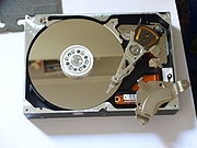
A disassembled and labeled 1997 hard drive. All major components were placed on a mirror, which created the symmetrical reflections.
Raw unformatted capacity of a hard disk drive is usually quoted with SI prefixes (metric system prefixes), incrementing by powers of 1000; today that usually means gigabytes (GB) and terabytes (TB). This is conventional for data speeds and memory sizes which are not inherently manufactured in power of two sizes, as RAM and Flash memory are. Hard disks by contrast have no inherent binary size as capacity is determined by number of heads, tracks and sectors.
This can cause some confusion because some operating systems may report the formatted capacity of a hard drive using binary prefix units which increment by powers of 1024.
A one terabyte (1 TB) disk drive would be expected to hold around 1 trillion bytes (1,000,000,000,000) or 1000 GB; and indeed most 1 TB hard drives will contain slightly more than this number. However some operating system utilities would report this as around 931 GB or 953,674 MB, whereas the correct units would be 931 GiB or 953,674 MiB. (The actual number for a formatted capacity will be somewhat smaller still, depending on the file system). Following are the correct ways of reporting one Terabyte.
SI prefixes (Hard Drive) equivalent Binary prefixes (OS) equivalent
1 TB (Terabytes) 1 * 10004 B 0.9095 TiB (Tebibytes) 0.9095 * 10244 B
1000 GB (Gigabytes) 1000 * 10003 B 931.3 GiB (Gibibytes) 931.3 * 10243 B
1,000,000 MB (Megabytes) 1,000,000 * 10002 B 953,674.3 MiB (Mebibytes) 953,674.2 * 10242 B
1,000,000,000 KB (Kilobytes) 1,000,000,000 * 1000 B 976,562,500 KiB (Kibibytes) 976,562,500 * 1024 B
1,000,000,000,000 B (bytes) – 1,000,000,000,000 B (bytes) –
Microsoft Windows reports disk capacity both in a decimal integer to 12 or more digits and in binary prefix units to three significant digits.
The capacity of an HDD can be calculated by multiplying the number of cylinders by the number of heads by the number of sectors by the number of bytes/sector (most commonly 512). Drives with the ATA interface and a capacity of eight gigabytes or more behave as if they were structured into 16383 cylinders, 16 heads, and 63 sectors, for compatibility with older operating systems. Unlike in the 1980s, the cylinder, head, sector (C/H/S) counts reported to the CPU by a modern ATA drive are no longer actual physical parameters since the reported numbers are constrained by historic operating-system interfaces and with zone bit recording the actual number of sectors varies by zone. Disks with SCSI interface address each sector with a unique integer number; the operating system remains ignorant of their head or cylinder count.
The old C/H/S scheme has been replaced by logical block addressing. In some cases, to try to “force-fit” the C/H/S scheme to large-capacity drives, the number of heads was given as 64, although no modern drive has anywhere near 32 platters.
Formatted disk overhead
For a formatted drive, the operating system’s file system internal usage is another, although minor, reason why a computer hard drive or storage device’s capacity may show its capacity as different from its theoretical capacity. This would include storage for, as examples, a file allocation table (FAT) or inodes, as well as other other operating system data structures. This file system overhead is usually less than 1% on drives larger than 100 MB. For RAID drives, data integrity and fault-tolerance requirements also reduce the realized capacity. For example, a RAID1 drive will be about half the total capacity as a result of data mirroring. For RAID5 drives with x drives you would lose 1/x of your space to parity. RAID drives are multiple drives that appear to be one drive to the user, but provide some kind of fault-tolerance.
A general rule of thumb to quickly convert the manufacturer’s hard disk capacity to the standard Microsoft Windows formatted capacity is 0.93*capacity of HDD from manufacturer for HDDs less than a terabyte and 0.91*capacity of HDD from manufacturer for HDDs equal to or greater than 1 terabyte.
Form factors
5¼″ full height 110 MB HDD,
2½″ (8.5 mm) 6495 MB HDD,
US/UK pennies for comparison.
Six hard drives with 8″, 5.25″, 3.5″, 2.5″, 1.8″, and 1″ disks, partially disassembled to show platters and read-write heads, with a ruler showing inches.
Before the era of PCs and small computers, hard disks were of widely varying dimensions, typically in free standing cabinets the size of washing machines (e.g. DEC RP06 Disk Drive) or designed so that dimensions enabled placement in a 19″ rack (e.g. Diablo Model 31).6
With increasing sales of small computers having built in floppy-disk drives (FDDs), HDDs that would fit to the FDD mountings became desirable, and this led to the evolution of the market towards drives with certain Form factors, initially derived from the sizes of 8″, 5.25″ and 3.5″ floppy disk drives. Smaller sizes than 3.5″ have emerged as popular in the marketplace and/or been decided by various industry groups.
* 8 inch: 9.5 in × 4.624 in × 14.25 in (241.3 mm × 117.5 mm × 362 mm)
In 1979, Shugart Associates’ SA1000 was the first form factor compatible HDD, having the same dimensions and a compatible interface to the 8″ FDD.
* 5.25 inch: 5.75 in × 1.63 in × 8 in (146.1 mm × 41.4 mm × 203 mm)
This smaller form factor, first used in an HDD by Seagate in 1980, was the same size as full height 5¼-inch diameter FDD, i.e., 3.25 inches high. This is twice as high as “half height” commonly used today; i.e., 1.63 in (41.4 mm). Most desktop models of drives for optical 120 mm disks (DVD, CD) use the half height 5¼″ dimension, but it fell out of fashion for HDDs. The Quantum Bigfoot HDD was the last to use it in the late 1990s, with “low-profile” (≈25 mm) and “ultra-low-profile” (≈20 mm) high versions.
* 3.5 inch: 4 in × 1 in × 5.75 in (101.6 mm × 25.4 mm × 146 mm) = 376.77344 cm³
This smaller form factor, first used in an HDD by Rodime in 1984, was the same size as the “half height” 3½″ FDD, i.e., 1.63 inches high. Today has been largely superseded by 1-inch high “slimline” or “low-profile” versions of this form factor which is used by most desktop HDDs.
* 2.5 inch: 2.75 in × 0.374–0.59 in × 3.945 in (69.85 mm × 9.5–15 mm × 100 mm) = 66.3575 cm³-104.775 cm³
This smaller form factor was introduced by PrairieTek in 1988; there is no corresponding FDD. It is widely used today for hard-disk drives in mobile devices (laptops, music players, etc.) and as of 2008 replacing 3.5 inch enterprise-class drives. It is also used in the Xbox 360 and Playstation 3 video game consoles. Today, the dominant height of this form factor is 9.5 mm for laptop drives, but high capacity drives used to have a height of 12.5 mm. Enterprise-class drives can have a height up to 15 mm.
* 1.8 inch: 54 mm × 8 mm × 71 mm = 30.672 cm³
This form factor, originally introduced by Integral Peripherals in 1993, has evolved into the ATA-7 LIF with dimensions as stated. It is increasingly used in digital audio players and subnotebooks. An original variant exists for 2–5 GB sized HDDs that fit directly into a PC card expansion slot. These became popular for their use in iPods and other HDD based MP3 players.
* 1 inch: 42.8 mm × 5 mm × 36.4 mm
This form factor was introduced in 1999 as IBM’s Microdrive to fit inside a CF Type II slot. Samsung calls the same form factor “1.3 inch” drive in its product literature.
* 0.85 inch: 24 mm × 5 mm × 32 mm
Toshiba announced this form factor in January 2004 for use in mobile phones and similar applications, including SD/MMC slot compatible HDDs optimized for video storage on 4G handsets. Toshiba currently sells a 4 GB (MK4001MTD) and 8 GB (MK8003MTD) version and holds the Guinness World Record for the smallest hard disk drive.
3.5″ and 2.5″ hard disks currently dominate the market.
By 2009 all manufacturers had discontinued the development of new products for the 1.3-inch, 1-inch and 0.85-inch form factors due to falling prices of flash memory,
The inch-based nickname of all these form factors usually do not indicate any actual product dimension (which are specified in millimeters for more recent form factors), but just roughly indicate a size relative to disk diameters, in the interest of historic continuity.
Other characteristics
Data transfer rate
As of 2008, a typical 7200rpm desktop hard drive has a sustained “disk-to-buffer” data transfer rate of about 70 megabytes per second. This rate depends on the track location, so it will be highest for data on the outer tracks (where there are more data sectors) and lower toward the inner tracks (where there are fewer data sectors); and is generally somewhat higher for 10,000rpm drives. A current widely-used standard for the “buffer-to-computer” interface is 3.0 Gbit/s SATA, which can send about 300 megabyte/s from the buffer to the computer, and thus is still comfortably ahead of today’s disk-to-buffer transfer rates. Data transfer rate (read/write) can be measured by writing a large file to disk using special file generator tools, then reading back the file. Transfer rate can be influenced by file system fragmentation and the layout of the files.
Seek time
Seek time currently ranges from just under 2 ms for high-end server drives, to 15 ms for miniature drives, with the most common desktop type typically being around 9 ms. There has not been any significant improvement in this speed for some years. Some early PC drives used a stepper motor to move the heads, and as a result had access times as slow as 80–120 ms, but this was quickly improved by voice coil type actuation in the late 1980s, reducing access times to around 20 ms.
Power consumption
Power consumption has become increasingly important, not just in mobile devices such as laptops but also in server and desktop markets. Increasing data center machine density has led to problems delivering sufficient power to devices (especially for spin up), and getting rid of the waste heat subsequently produced, as well as environmental and electrical cost concerns (see green computing). Similar issues exist for large companies with thousands of desktop PCs. Smaller form factor drives often use less power than larger drives. One interesting development in this area is actively controlling the seek speed so that the head arrives at its destination only just in time to read the sector, rather than arriving as quickly as possible and then having to wait for the sector to come around (i.e. the rotational latency). Many of the hard drive companies are now producing Green Drives that require much less power and cooling. Many of these ‘Green Drives’ spin slower (<5400 RPM compared to 7200 RPM, 10,000 RPM, and 15,000 RPM) and also generate less waste heat.
Also in Server and Workstation systems where there might be multiple hard disk drives, there are various ways of controlling when the hard drives spin up (highest power draw).
On SCSI hard disk drives, the SCSI controller can directly control spin up and spin down of the drives.
On Parallal ATA (aka PATA) and SATA hard disk drives, some support Power-up in standby or PUIS. The hard disk drive will not spin up until the controller or system BIOS issues a specific command to do so. This limits the power draw or consumption upon power on.
On newer SATA hard disk drives, there is Staggered Spin Up feature. The hard disk drive will not spin up until the SATA Phy comes ready (communications with the host controller starts). The details are in the SATA specification – reference needed.
To further control or reduce power draw and consumption, the hard disk drive can be spun down to reduce it’s power consumption.
Audible noise
Measured in dBA, audible noise is significant for certain applications, such as PVRs, digital audio recording and quiet computers. Low noise disks typically use fluid bearings, slower rotational speeds (usually 5,400 rpm) and reduce the seek speed under load (AAM) to reduce audible clicks and crunching sounds. Drives in smaller form factors (e.g. 2.5 inch) are often quieter than larger drives.
Shock resistance
Shock resistance is especially important for mobile devices. Some laptops now include active hard drive protection that parks the disk heads if the machine is dropped, hopefully before impact, to offer the greatest possible chance of survival in such an event. Maximum shock tolerance to date is 350 Gs for operating and 1000 Gs for non-operating.
Access and interfaces
Question book-new.svg
This section needs additional citations for verification.
Please help improve this article by adding reliable references. Unsourced material may be challenged and removed. (July 2009)
Hard disk drives are accessed over one of a number of bus types, including parallel ATA (P-ATA, also called IDE or EIDE), Serial ATA (SATA), SCSI, Serial Attached SCSI (SAS), and Fibre Channel. Bridge circuitry is sometimes used to connect hard disk drives to buses that they cannot communicate with natively, such as IEEE 1394, USB and SCSI.
Back in the days of the ST-506 interface, the data encoding scheme was also important. The first ST-506 disks used Modified Frequency Modulation (MFM) encoding, and transferred data at a rate of 5 megabits per second. Later on, controllers using 2,7 RLL (or just “RLL”) encoding increased the transfer rate by 50%, to 7.5 megabits per second; this also increased disk capacity by fifty percent.
Many ST-506 interface disk drives were only specified by the manufacturer to run at the lower MFM data rate, while other models (usually more expensive versions of the same basic disk drive) were specified to run at the higher RLL data rate. In some cases, a disk drive had sufficient margin to allow the MFM specified model to run at the faster RLL data rate; however, this was often unreliable and was not recommended. An RLL-certified disk drive could run on a MFM controller, but with 1/3 less data capacity and speed.
Enhanced small disk interface (ESDI) also supported multiple data rates (ESDI disks always used 2,7 RLL, but at 10, 15 or 20 megabits per second), but this was usually negotiated automatically by the disk drive and controller; most of the time, however, 15 or 20 megabit ESDI disk drives weren’t downward compatible (i.e. a 15 or 20 megabit disk drive wouldn’t run on a 10 megabit controller). ESDI disk drives typically also had jumpers to set the number of sectors per track and (in some cases) sector size.
Modern hard drives present a consistent interface to the rest of the computer, no matter what data encoding scheme is used internally. Typically a DSP in the electronics inside the hard drive takes the raw analog voltages from the read head and uses PRML and Reed–Solomon error correction to decode the sector boundaries and sector data, then sends that data out the standard interface. That DSP also watches the error rate detected by error detection and correction, and performs bad sector remapping, data collection for Self-Monitoring, Analysis, and Reporting Technology, and other internal tasks.
SCSI originally had just one signaling frequency of 5 MHz for a maximum data rate of 5 megabytes/second over 8 parallel conductors, but later this was increased dramatically. The SCSI bus speed had no bearing on the disk’s internal speed because of buffering between the SCSI bus and the disk drive’s internal data bus; however, many early disk drives had very small buffers, and thus had to be reformatted to a different interleave (just like ST-506 disks) when used on slow computers, such as early Commodore Amiga, IBM PC compatibles and Apple Macintoshes.
ATA disks have typically had no problems with interleave or data rate, due to their controller design, but many early models were incompatible with each other and couldn’t run with two devices on the same physical cable in a master/slave setup. This was mostly remedied by the mid-1990s, when ATA’s specification was standardised and the details began to be cleaned up, but still causes problems occasionally (especially with CD-ROM and DVD-ROM disks, and when mixing Ultra DMA and non-UDMA devices).
Serial ATA does away with master/slave setups entirely, placing each disk on its own channel (with its own set of I/O ports) instead.
FireWire/IEEE 1394 and USB(1.0/2.0) HDDs are external units containing generally ATA or SCSI disks with ports on the back allowing very simple and effective expansion and mobility. Most FireWire/IEEE 1394 models are able to daisy-chain in order to continue adding peripherals without requiring additional ports on the computer itself. USB however, is a point to point network and doesn’t allow for daisy-chaining. USB hubs are used to increase the number of available ports and are used for devices that don’t require charging since the current supplied by hubs is typically lower than what’s available from the built-in USB ports.
Disk interface families used in personal computers
Notable families of disk interfaces include:
* Historical bit serial interfaces — connect a hard disk drive (HDD) to a hard disk controller (HDC) with two cables, one for control and one for data. (Each drive also has an additional cable for power, usually connecting it directly to the power supply unit). The HDC provided significant functions such as serial/parallel conversion, data separation, and track formatting, and required matching to the drive (after formatting) in order to assure reliability. Each control cable could serve two or more drives, while a dedicated (and smaller) data cable served each drive.
o ST506 used MFM (Modified Frequency Modulation) for the data encoding method.
o ST412 was available in either MFM or RLL (Run Length Limited) encoding variants.
o Enhanced Small Disk Interface (ESDI) was an interface developed by Maxtor to allow faster communication between the processor and the disk than MFM or RLL.
* Modern bit serial interfaces — connect a hard disk drive to a host bus interface adapter (today typically integrated into the “south bridge”) with one data/control cable. (As for historical bit serial interfaces above, each drive also has an additional power cable, usually direct to the power supply unit.)
o Fibre Channel (FC), is a successor to parallel SCSI interface on enterprise market. It is a serial protocol. In disk drives usually the Fibre Channel Arbitrated Loop (FC-AL) connection topology is used. FC has much broader usage than mere disk interfaces, it is the cornerstone of storage area networks (SANs). Recently other protocols for this field, like iSCSI and ATA over Ethernet have been developed as well. Confusingly, drives usually use copper twisted-pair cables for Fibre Channel, not fibre optics. The latter are traditionally reserved for larger devices, such as servers or disk array controllers.
o Serial ATA (SATA). The SATA data cable has one data pair for differential transmission of data to the device, and one pair for differential receiving from the device, just like EIA-422. That requires that data be transmitted serially. Similar differential signaling system is used in RS485, LocalTalk, USB, Firewire, and differential SCSI.
o Serial Attached SCSI (SAS). The SAS is a new generation serial communication protocol for devices designed to allow for much higher speed data transfers and is compatible with SATA. SAS uses a mechanically identical data and power connector to standard 3.5″ SATA1/SATA2 HDDs, and many server-oriented SAS RAID controllers are also capable of addressing SATA hard drives. SAS uses serial communication instead of the parallel method found in traditional SCSI devices but still uses SCSI commands.
* Word serial interfaces — connect a hard disk drive to a host bus adapter (today typically integrated into the “south bridge”) with one cable for combined data/control. (As for all bit serial interfaces above, each drive also has an additional power cable, usually direct to the power supply unit.) The earliest versions of these interfaces typically had a 8 bit parallel data transfer to/from the drive, but 16 bit versions became much more common, and there are 32 bit versions. Modern variants have serial data transfer. The word nature of data transfer makes the design of a host bus adapter significantly simpler than that of the precursor HDD controller.
o Integrated Drive Electronics (IDE), later renamed to ATA, with the alias P-ATA (“parallel ATA”) retroactively added upon introduction of the new variant Serial ATA. The original name reflected the innovative integration of HDD controller with HDD itself, which was not found in earlier disks. Moving the HDD controller from the interface card to the disk drive helped to standardize interfaces, and to reduce the cost and complexity. The 40 pin IDE/ATA connection transfers 16 bits of data at a time on the data cable. The data cable was originally 40 conductor, but later higher speed requirements for data transfer to and from the hard drive led to an “ultra DMA” mode, known as UDMA. Progressively faster versions of this standard ultimately added the requirement for an 80 conductor variant of the same cable; where half of the conductors provides grounding necessary for enhanced high-speed signal quality by reducing cross talk. The interface for 80 conductor only has 39 pins, the missing pin acting as a key to prevent incorrect insertion of the connector to an incompatible socket, a common cause of disk and controller damage.
o EIDE was an unofficial update (by Western Digital) to the original IDE standard, with the key improvement being the use of direct memory access (DMA) to transfer data between the disk and the computer without the involvement of the CPU, an improvement later adopted by the official ATA standards. By directly transferring data between memory and disk, DMA eliminates the need for the CPU to copy byte per byte, therefore allowing it to process other tasks while the data transfer occurs.
o Small Computer System Interface (SCSI), originally named SASI for Shugart Associates System Interface, was an early competitor of ESDI. SCSI disks were standard on servers, workstations, Commodore Amiga and Apple Macintosh computers through the mid-90s, by which time most models had been transitioned to IDE (and later, SATA) family disks. Only in 2005 did the capacity of SCSI disks fall behind IDE disk technology, though the highest-performance disks are still available in SCSI and Fibre Channel only. The length limitations of the data cable allows for external SCSI devices. Originally SCSI data cables used single ended (common mode) data transmission, but server class SCSI could use differential transmission, either low voltage differential (LVD) or high voltage differential (HVD). (“Low” and “High” voltages for differential SCSI are relative to SCSI standards and do not meet the meaning of low voltage and high voltage as used in general electrical engineering contexts, as apply e.g. to statutory electrical codes; both LVD and HVD use low voltage signals (3.3 V and 5 V respectively) in general terminology.)


